Grab Your FREE Guide to Begin with Lighting. In accordance with Usb To Dmx Wiring Diagram you will find just four wires used in the cable.

Make A Dmx Tester Dmx Tester Dmx Lighting
The rear view is the end you solder from Here are the connections on each pin.

Dmx wiring diagram. 5 Pin Dmx Wiring Diagram Albertasafety Org. Data - Pair 1 Complement 2. This chart is based on the ANSI E127-2 standard for DMX cabling and is not intended for DMX-over-Ethernet wiring.
Uin 1 2- 4VDC Iin 325 A SEC. Xlr 4 Pin Wiring Schematics Online. Connect the network cables DMX DMX- and DMX shielding wire the orangewhite orange and brown wire in a CAT5 cable to the DMX in DMX in- and DMX in shield connector respectively.
Wire Color and Function. 3 Pin Dmx Wiring Diagram wiring diagram is a simplified usual pictorial representation of an electrical circuit. Dmx Pinout Tehno.
4 Pin Mini Xlr Wiring Diagram Unique Av Micro 4pin Wiring. Configuring your driver over DMX in Download the software from your drivers product web page and connect a USB tongle to DMX in to configure your driver. DMX Digital MultipleX is a communications protocol used mainly to control stage lighting.
DMX512 data are transmitted over a differential pair using EIA-485 voltage levels. Optional Data Pair 2 5. Wiring Diagram 5 Pin Dmx Dmx Led Controller Wiring Diagram.
WIRING INSTRUCTIONS DMX Dimming Page 1 DIMMING DRIVER WIRING SCHEMES. These diagrams are not intended to specify all equipment necessary for a. Bioart ideas3 Pin Dmx Wiring Diagram leads direct terminators xlr connectors with the resistor already fitted are available on our e shop order dmxt for the 3 pin version or dmx5t for the 5 pin the wiring of the xlr connectors in a dmx cable is shown below xlr wiring standards diagram pin out 3 pin audio 5 3 pin xlr wiring standard 3 pin xlr.
It shows the components of the circuit as simplified shapes and the capability and signal links in the middle of the devices. The above diagram shows you the pin numbering for both Male and Female XLR connectors from the front and the rear view. The start of a packet is signified by a break of at least 88 uS.
Here are 2 ways to wire DMX - its easier than you thinkLinks. Data Pair 1 True 3. DMX512 WIRING GUIDE ARCHITECTURAL V G-R-O U T P U T CH1 2 B-3 W-4 SR-2102BEA-RJ45 D DMX512 Decoder C I N P U T 1 2 2 4 D C V V-DMX Sta rt C h nel PRI.
Pin 1 DMX DATA WhiteOrange Pin 2 DMX DATA - Orange Pin 3 AUX DMX DATA WhiteGreen Pin 4 NOT USED Blue Pin 5 NOT USED WhiteBlue Pin 6 ALT DMX DATA - Green Pin 7 GROUNDCOMMON WhiteBrown Pin 8 AUX GROUNDCOMMON Brown. To be able to build a USB cable you need to collect these substances. Optional Data - Pair 2 4.
Cat5 cable commonly used for networking and telecommunications has been tested by ESTA for use with DMX512A. Wiring diagrams are examples of typical installations intended to illustrate the number of wires that must be run to fixture. Dmx Wiring Diagrams Sirs-E Usb To Dmx Wiring Diagram.
DMX Digital MultipleX is a communications protocol used mainly to control stage lighting. DMX Wiring Connections for Cat 5 or equivalent wire. Network wiring consists of a shielded twisted pair with a characteristic impedance of 120 Ohms with a termination resistor at the end of the cable furthest from the.
It is meant to help all the average user in building a correct program. Equivalent XLR Pin 1 - WhiteOrange. Data are sent with 1 start bit and 2 stop.
7 Pin Trailer Wiring Get Wiring Diagram. Cat-5 cable of desired length. Xlr Connector Wiring Diagram Lovely Wiring Xlr Connectors.
Typically it utilizes black black. DMX Wiring Controlling lighting with low voltage signals DMX leads are used to send low voltage control signals to DMX equipped lighting units such as dimmer packs scanners lighting effects lasers etc. Leads Direct carries a huges range of these cables from stock in lengths from 1m up to 30m and they can be custom manufactured in any length up to 100m.
Uout 4x12-2 4VDC Io ut 4x8A Pout 4x96-192W TEMP RANGE-20-50 5 0-9 1 2 3 4 5 6 7 8 Pin1D at Pin2D at - Pin7GND Pin8GND 1 2 3 4 5 6 7 8 R G B R G B W W P o w e r S u p p l y.

Rj45 Female Connector Wiring Diagram Wiring Diagram Dmx Power

Pin By Shaiful Nizam On Audio Studio Wiring Diagram Diagram Subwoofer Wiring

Kenwood Car Stereo Wiring Diagram Car Audio Car Stereo Systems Car Audio Installation

How To Wire A Dmx System With Rgb Colour Led Strip Lights Wiring Diagram Led Strip Lighting Strip Lighting Wiring Diagram

Armonia Pro Audio Suite User Guide Conexion

Pic16f73 And Max485 Interface Circuit Diagram Circuit Diagram Diagram Pic Microcontroller

Ps2 Keyboard To Usb Wiring Diagram Wiring Diagram In 2021 Wiring Diagram Usb Wiring Diagram Electrical Wiring Diagram

Xlr Pinouts Another Tech Tip From Www Videowestinc Com Line Level Connector Audio

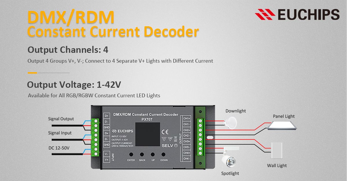
Constant Current Dmx Decoder Px707 4 Channels 200 1600ma Per Channel The Current Of Each Channel Can Be Set Separately Dmx Led Controller Constant Current

0 10 Volt Dimming Wiring Diagram Dmx Wiring Diagram Arduino

Usb To Dmx Schematic Electronic Schematics Dmx Usb

Esp8266 Artnet To Dmx Dmx Floor Plans Technician

My Blog About The Xlr Pinout About Me Blog Line Level Dmx Lighting

Dmx To Rj45 Wiring Diagram Dmx Discover Your Wiring Diagram Rj45 Wiring Diagram Dmx Wiring Diagram

Xlr Wiring Standard Diagram Dmx Wire Audio

Example Wiring Diagram For Controlling A Ws2812b Led Strip With A Force Sensing Linear Potentiometer Fslp And An Arduino Led Diy Led Diagram


